JE10: Ion-cyclotron wave (ICW) propagation and mode conversion
The ion-cyclotron wave (ICW) is a short-wavelength cold-plasma wave that occurs when an electromagnetic wave is pumped into a plasma threaded with a magnetic field that is oblique to the direction of wave propagation. This situation is encountered in the laboratory in ion-cyclotron resonance heating (ICRH) in tokamaks.
In this problem tokamak-like parameters are used to initialize the plasma. The domain is assumed to be \(x\in[2.83, 3.17]\). The tokamak major radius is assumed to be \(R_0=3.0\) meters. The density profile is computed using
where, \(s\) is the species index, \(n_{0s}\) are \(n_{ws}\) reference number densities, and the \(f(x)\) profile is computed from
Here \(a\) is the wall radius, and \(\alpha\) is a constant that controls the shape of the profile. We have set \(a=1\), \(\alpha=2\) and \(\beta = 1\) to give a quadratic density profile. An external magnetic field is initialized using \(B_x(x) = B_z(x)/10\) with \(B_z(x) = B_0 R_0/x\), where \(B_0 = 4\) Tesla. The external field is held fixed during the simulation.
The plasma contains three species: electrons, deuterium and Helium-3. The reference densities are set to \(4\times 10^{19}\), \(3.6\times 10^{19}\) and \(2\times 10^{18}\) \(\mathrm{m}^{-3}\) respectively. The wall reference densities are all set to 0.
The plasma is illuminated with a antenna source operating at a frequency of \(40.5\) MHz. The antenna current source is specified using
where \(f_d = 40.5\times 10^6\) Hz is the drive frequency and \(t_0=5/f_d\) is the time at which the source turns on completely.
Two cases are considered: high-field incidence (antenna is on the left) and low-field incidence (antenna is on the right). Results are presented below.
Notes on the simulations
These simulations are quite complex (over 500 lines of Lua) as there are three fluid species and a static background magnetic field. This means that we need to create 4 solvers (one for each species and the EM field) and take into account the Lorentz force on each species and the current contributions from each species. Further, the static field also exerts a Lorentz force on each species.
One observation was that the simulation needs to be run close to the allowed CFL limit (of 1.0 in 1D) in order for the solutions to look reasonable. This means, unfortunately, that there need to be enough cells in the domain so that the time-step from speed of light constraint is smaller than that allowed by the plasma frequency. Another option is to treat the electron physics implicitly.
High-field incidence
In the high-field incidence simulation the antenna is placed in the first cell (left) in the domain. In this case there is strong mode conversion of the fast wave to the ICW. The simulation needs to be run for around 100 periods before the mode conversion is clearly visible.
The oblique angle of propagation results in all three electric field components. The \(E_y\) component is domainated by the fast wave and shows a standing wave pattern. The \(E_z\) component is dominated by the mode-converted ICW while the \(E_x\) shows both. At the mode conversion layer the \(E_x\) field shows a sharp gradient. See movie of the simulation.
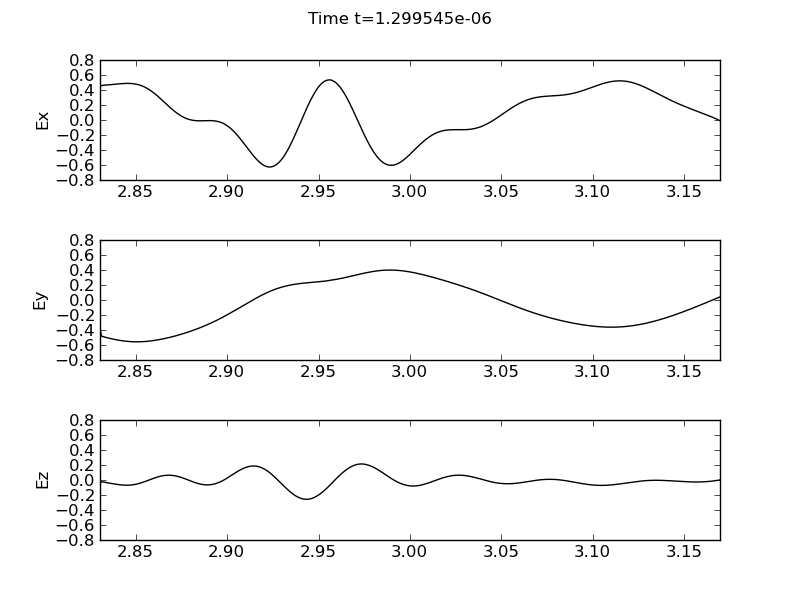
Electric field components, \(E_x\) (top panel), \(E_y\) (middle panel) and \(E_z\) (bottom panel) for high-field incidence (antenna is on the left). The plot is around the time when the ICW mode conversion is starting to occur. [s74]
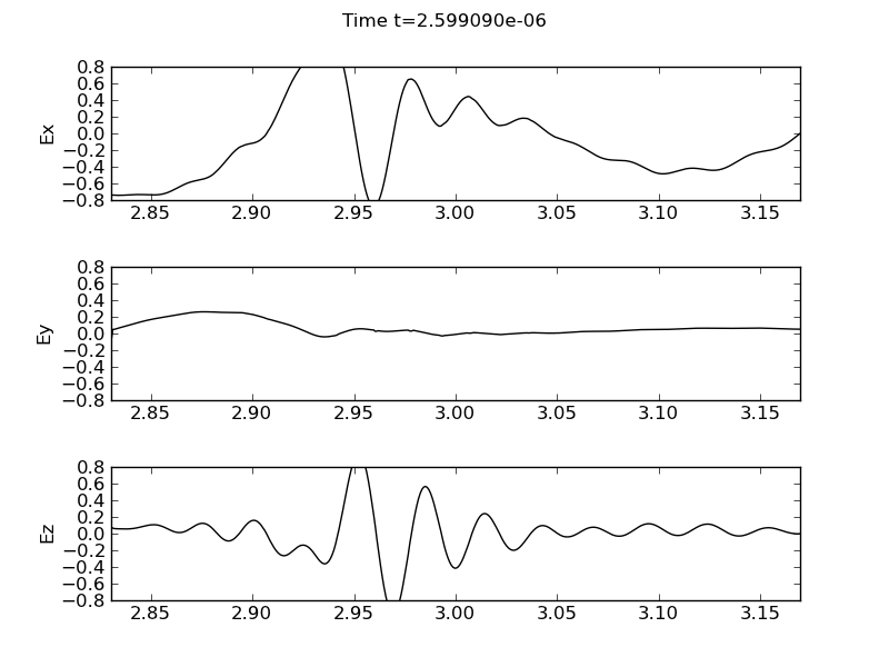
Electric field components, \(E_x\) (top panel), \(E_y\) (middle panel) and \(E_z\) (bottom panel) for high-field incidence.
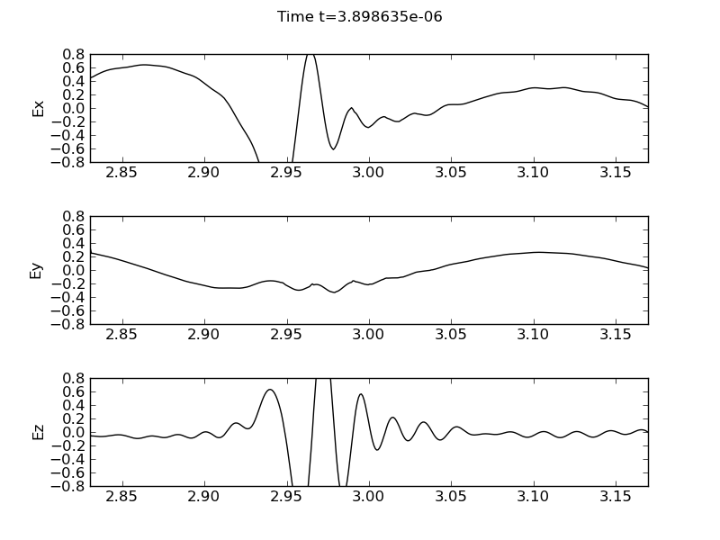
Electric field components, \(E_x\) (top panel), \(E_y\) (middle panel) and \(E_z\) (bottom panel) for high-field incidence.
Low-field incidence
In the low-field incidence simulation the antenna is placed in the last cell (right) in the domain. In this case the mode conversion is weaker than in the high-field incidence case. The differences are clearly visible from the high-field incidence case in the \(E_x\) and \(E_z\). The gradients are much weaker while the amplitudes are smaller. See movie of the simulation.
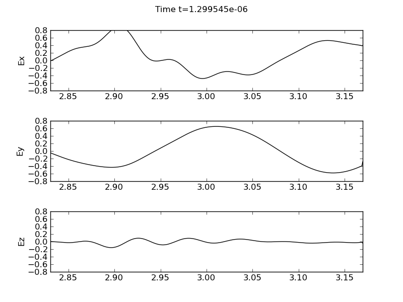
Electric field components, \(E_x\) (top panel), \(E_y\) (middle panel) and \(E_z\) (bottom panel) for low-field incidence (antenna is on the right). The plot is around the time when the ICW mode conversion is starting to occur. [s76]
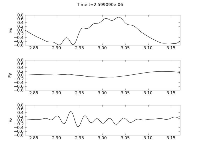
Electric field components, \(E_x\) (top panel), \(E_y\) (middle panel) and \(E_z\) (bottom panel) for low-field incidence.
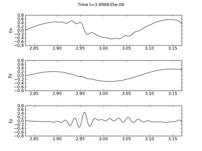
Electric field components, \(E_x\) (top panel), \(E_y\) (middle panel) and \(E_z\) (bottom panel) for low-field incidence.
Conclusions
A multi-fluid model is used to peform ICW mode conversion simulations. Strong mode conversion is seen in the high-field incidence case. The algorithm needs to be run close to the allowed CFL limit to avoid unphysical oscillations in the electric field. This can be avoided by using an implicit scheme for the electron motion.
