JE9: Tunneling through an electron-cyclotron cutoff layer
In this note I study the propagation of an radio-frequency (RF) wave into a electron-cyclotron cutoff layer. As in the plasma beach problem, the ions are assumed to be stationary and are not evolved. The plasma is initialized with a uniform density and is threaded with a non-uniform static transverse field. This static field exerts a Lorentz force on the electrons but is not evolved or included in the electric field update equations. What this means physically is that the static field is assumed to be created from a set of external coils and hence its curl is zero.
The domain is one-dimensional, \(0 <x < 0.14\), with open boundary conditions on either end. The plasma density is set to \(1\times10^{17}\)/m \(^3\). An electromagnetic wave is driven by a current applied at the center of the last cell, i.e.,
where \(f_d = 15\times 10^9\) Hz is the drive frequency and \(t_0=10/f_d\) is the time at which the source turns on completely. The second factor in the above equation ramps up the source slowly so as to avoid exciting small scale oscillations and extraneous modes. The static magnetic field is set to
where \(B_0 = 0.536\) Tesla, \(R_0 = 5\times10^{-3}\) and \(x_c = 0.04\) m is the location at which the electron cyclotron frequency matches the drive frequency. The electron temperature is set to \(1\times10^{-2}\) eV, i.e. the electrons are cold.
The problem was run on a 200 cell grid and run to \(1.4\) ns. The results of \(E_x\) and \(E_y\) are plotted below at different time frames. The results show that the EM wave suffers a cutoff at \(x_c\) and tunnels into the cyclotron layer. It is also seen that the electrostatic field develops a sharp spike around the cutoff layer as the wave number becomes infinite there.
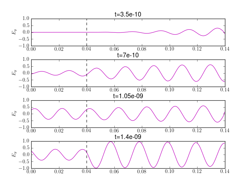
The electric field (\(E_y\)) of the EM wave at different times. The black dashed line shows the location of the cyclotron cutoff. The wave tunnels through the electron cyclotron resonance layer, forming a distinct standing wave pattern late in time. The simulation input file is at s72.

The electrostatic field (\(E_x\)) at different times. The black dashed line shows the location of the cyclotron cutoff. A very sharp spike develops at the cutoff location as the wave number becomes infinite.
A simulation was performed with the same parameters but with 400 cells and was run to 50 ns. The electrostatic field component is shown below.
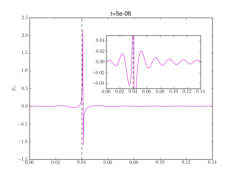
The electrostatic field (\(E_x\)) at \(t=50\) ns. The black dashed line shows the location of the cyclotron cutoff. The plot shows the sharp spike formed due to the wave number becoming infinite. The inset plot is a zoom to show the electrostatic field around the resonance layer. The simulation input file is at s73.
Conclusions
In this simulation the propagation of a wave into an electron cyclotron resonance layer is shown. The EM wave suffers a cutoff at the resonance layer but tunnels through. The electrostatic field shows a sharp spike due to the wave number becoming infinite at the resonance layer. However, the finite size of the grid means that the spike can only be resolved to the smallest grid size. Even though the linear theory predicts unlimited growth of the wave number, when the field amplitude gets large enough the plasma will become non-linear and the linear theory is no longer valid. The simulations show a characteristic feature of cyclotron cutoff layers: sharp gradients in the electrostatic fields and a sudden change in the electromagnetic wave amplitude.